


 Phone: +371 66 065 303
 E-mail:
For designers
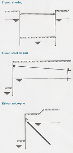
If the structural and constructional requirements placed on a sheet pile wall call for an anchorage, then propping the walls against each other is one way of doing this, e.g. in trenches for installing buried services.
However, in most cases the wall will have to be anchored back into the ground. Structural and constructional requirements dictate the choice and design of an anchorage. Critical for the design is the support reaction A resulting from the structural calculations for the sheet pile wall and the analysis of the lower slip plane.
The waling transfers the forces from the sheet pile wall to the anchor and at the same time helps to align and stiffen the wall. The anchor transfers the support reaction of the sheet pile wall via the waling to the anchorage itself.
And the task of the anchorage is to transfer the forces from main wall to the subsoil. When using round steel tie rods, the anchorage is achieved with anchor plate or anchor wall.
When using anchor piles, e.g. driven steel piles, driven micropiles, the force from the sheet pile wall is transferred to the subsoil via the skin friction of the pile.
 Design of anchorage elements
Anchor wall, walings, capping beams and end plates
In the case of primarily constant loads, it is necessary to verify the structural safety to DIN 1800 or DIN EN 1993-5. A higher partial safety may need to be considered for walings and capping beams. In the case of primarily varying loads, it is necessary to verify the fatigue strength to DIN 19704-1. Reference should also be made to DIN 18800-1.
Killed steels to DIN EN 10025 should generally be used. Close-tolerance bolts, grade 4.6 or higher, should be used at bolted joints in walings and capping beams. Verification of fatigue strength to DIN 18800-1 is also required.
Round steel tie rods and waling bolts
Anchors are generally subjected to mostly static loads. Significant cyclic loadings occur in anchors in certain instances only, but more frequently in waling bolts. Steels to DIN EN 10025 should be used for round steel tie rods and waling bolts. Steel grade S 355 J2+N is normally selected. The anchor forces due to the loads according to load case 2 should generally be used for the design for primarily static loads. Verification of structural safety is to be carried out according to DIN 18800-1 section 8.2.2.3. The reduction factors relevant for load cases 1 to 3 should be taken into account.
DIN EN 14199 applies for the design and construction of sheet pile wall anchorages with grouted anchors. Only fully killed steels may be used in situations with primarily cyclic loadings. Verification of structural safety is to be carried out according to DIN 18800-1 section 8.2.1.5. If the basic static load is equal to or less than the amplitude of the cyclic loading, designer is recommended to prestress the anchors, or waling bolts, to a value higher than the amplitude of the stress in a controlled and permanent way.
Waling design
Normally, a walling is in the form of two latticed steel channels, positioned with their webs perpendicular to the sheet pile wall. Chanel types UPE or UNP can be used as required. However, other steel sections such as single LARSSEN piles and double T sections or a capping beam solution is possible.
Reinforced concrete walings are used mainly in conjunction with anchor walls, apart from structures with anchor piles and when compensating for sheet pile walls that are out of position.
The necessary spacing between the two channel sections is achieved with further channel sections or web plates (so called latticing) welded to the channels at intervals depending on the pile width. This spacing between the channels depends on the diameter and angle of anchors, and must be large enough to ensure that the anchors do not touch the waling.
The channels of the walling will have to be strengthened where heavy-duty anchors are being used or where they are connected directly to the waling . Waling segments are supplied in lengths equal to a multiple of the anchor spacing. Joints between waling segments must be positioned to minimize the stresses. A full splice equal to the cross-sectional area is unnecessary, but the calculated internal forces must be covered.
Splice joints are generally in the form of bolted channel sections supplied with the necessary bolt holes ready to install. The waling sections are pre-drilled for the splice on one side of the joint only; the other side is drilled to suit on site. Welded joints do not need to be spliced provided they are staggered and fully connected in the manner of a structural steelwork connection.
However, in most cases the wall will have to be anchored back into the ground. Structural and constructional requirements dictate the choice and design of an anchorage. Critical for the design is the support reaction A resulting from the structural calculations for the sheet pile wall and the analysis of the lower slip plane.
The waling transfers the forces from the sheet pile wall to the anchor and at the same time helps to align and stiffen the wall. The anchor transfers the support reaction of the sheet pile wall via the waling to the anchorage itself.
And the task of the anchorage is to transfer the forces from main wall to the subsoil. When using round steel tie rods, the anchorage is achieved with anchor plate or anchor wall.
When using anchor piles, e.g. driven steel piles, driven micropiles, the force from the sheet pile wall is transferred to the subsoil via the skin friction of the pile.
Design of anchorage elementsAnchor wall, walings, capping beams and end plates
In the case of primarily constant loads, it is necessary to verify the structural safety to DIN 1800 or DIN EN 1993-5. A higher partial safety may need to be considered for walings and capping beams. In the case of primarily varying loads, it is necessary to verify the fatigue strength to DIN 19704-1. Reference should also be made to DIN 18800-1.
Killed steels to DIN EN 10025 should generally be used. Close-tolerance bolts, grade 4.6 or higher, should be used at bolted joints in walings and capping beams. Verification of fatigue strength to DIN 18800-1 is also required.
Round steel tie rods and waling bolts
Anchors are generally subjected to mostly static loads. Significant cyclic loadings occur in anchors in certain instances only, but more frequently in waling bolts. Steels to DIN EN 10025 should be used for round steel tie rods and waling bolts. Steel grade S 355 J2+N is normally selected. The anchor forces due to the loads according to load case 2 should generally be used for the design for primarily static loads. Verification of structural safety is to be carried out according to DIN 18800-1 section 8.2.2.3. The reduction factors relevant for load cases 1 to 3 should be taken into account.
DIN EN 14199 applies for the design and construction of sheet pile wall anchorages with grouted anchors. Only fully killed steels may be used in situations with primarily cyclic loadings. Verification of structural safety is to be carried out according to DIN 18800-1 section 8.2.1.5. If the basic static load is equal to or less than the amplitude of the cyclic loading, designer is recommended to prestress the anchors, or waling bolts, to a value higher than the amplitude of the stress in a controlled and permanent way.
Normally, a walling is in the form of two latticed steel channels, positioned with their webs perpendicular to the sheet pile wall. Chanel types UPE or UNP can be used as required. However, other steel sections such as single LARSSEN piles and double T sections or a capping beam solution is possible.
Reinforced concrete walings are used mainly in conjunction with anchor walls, apart from structures with anchor piles and when compensating for sheet pile walls that are out of position.
The necessary spacing between the two channel sections is achieved with further channel sections or web plates (so called latticing) welded to the channels at intervals depending on the pile width. This spacing between the channels depends on the diameter and angle of anchors, and must be large enough to ensure that the anchors do not touch the waling.
The channels of the walling will have to be strengthened where heavy-duty anchors are being used or where they are connected directly to the waling . Waling segments are supplied in lengths equal to a multiple of the anchor spacing. Joints between waling segments must be positioned to minimize the stresses. A full splice equal to the cross-sectional area is unnecessary, but the calculated internal forces must be covered.
Splice joints are generally in the form of bolted channel sections supplied with the necessary bolt holes ready to install. The waling sections are pre-drilled for the splice on one side of the joint only; the other side is drilled to suit on site. Welded joints do not need to be spliced provided they are staggered and fully connected in the manner of a structural steelwork connection.
